Usage and Operation Principles Explained
Filtration is the process of separating a suspended solid such as a precipitate from the liquid in which it is already suspended by straining it through a porous medium that can be penetrated easily by liquid. Industrial filtration methods are classified according to the driving force that is applied. Pressure and vacuum filtration techniques are the most commonly applied and involve the use of perlite filter aid as precoat and/or body feed. Major aspects of most commonly applied pressure and vacuum filtration techniques are presented below.


Plate and Frame Pressure Filters
GENERAL FACTS
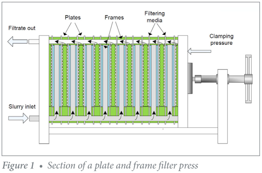
The simplest batch pressure filter is the plate filter where the slurry occupies the space between two vertical plates clamped together by an externally operated screw system or hydraulic ram.1 A series of hollow frames separate the plates which are placed side by side and hung from two parallel rails on either side of the plates. The filtering medium is placed against the sides of the plates and the slurry is pumped between them. °e slurry pressure presses the pulp against the medium forcing the liquid through the cloth and leaving the solids as a cake, on both surfaces of the frame.
The plates are usually square shaped with ribbed or studded surfaces. Circular plates are also available in industry. The size of plates varies from about 450 × 450 mm to 2000 × 2000 mm and frames from 10 mm to 202 mm in thickness. They are usually made of steel to withstand pressures in excess of 1800 kPa. The usual number of plates in commercial practice varies between 25 and 50 but up to 100 plate filters are reported.
This type of filter is characterized by a wide variety of sizes, configurations, plate supports and degrees of automation.2 There are manual filter presses as well as automatic discharge presses where the plates are hydraulically opened and the cakes fall under their own weight. For sticky cakes, manual intervention is required. Filtration pressures can be up to several thousand pounds per square inch gauge (psig). A new development of the plate and frame filter press is a contained filter press that employs a horizontal pressure filter, tubular in construction, with circular plates. The circular plates with welded metal or synthetic media are contained in a pressurized housing. This allows for pressure filtration, cake washing, and vacuum or pressure drying. After the cycle is completed, the housing is moved and automatic cake discharge is via scraper knives that move between the plates.
PRECOAT AND BODYFEED
The first step in filtration belongs to the formation of the precoat, a thin layer (1.5 to 3.0 mm or 1/16 – 1/8 inch) that protects the septum, ensures clarity and helps ˙ow control and solids removal. The septum serves principally as cake support. The filter aid forms a porous and permeable layer on the septum and becomes the filtering medium that traps the solids and prevents them from blinding the septum. Careful selection of the precoat filter aid grade ensures fast, uninterrupted and efficient filtration.
First, a slurry is made from filtered liquid, or sometimes water, and filter aid. The concentration should be low as possible (normally 0.5 % by weight). Agitation in the precoat tank should be sufficient to keep the filter aid in suspension. Excessive agitation for extended time is discouraged as it may cause excessive breakdown of the particles. Filter aids should be added at 500 to 1200 g/m² (10 – 25 lbs/100ft²) of filter area. The precoat is formed by recirculating the filter aid slurry through the filter. The coarser particles deposit themselves first on the screen followed by smaller ones. A precoating rate of 40 L/m²/min. (1 GPM/ft²) is normal. Much lower rates are used with higher viscosity liquids. During precoating process, the pressure difference should be over 0.07 kg/cm² (1 psi). Precoating liquor should clear up within 10 to 15 minutes.3
Addition of filter aid to the liquid to be filtered is referred to as bodyfeed. The type and grade as well as quantity to be added is vitally important to obtain the highest filtration flowrate consistent with the clarification required. Filter aid dosage varies with the solids content and other variables specific to each application. Generally speaking, a dosage of ½ of the percent solids by weight is usually enough. Bodyfeed can be added directly to the tank of liquid to be filtered, or dosed from a slurry tank into the filter inlet.3
Leaf Filters
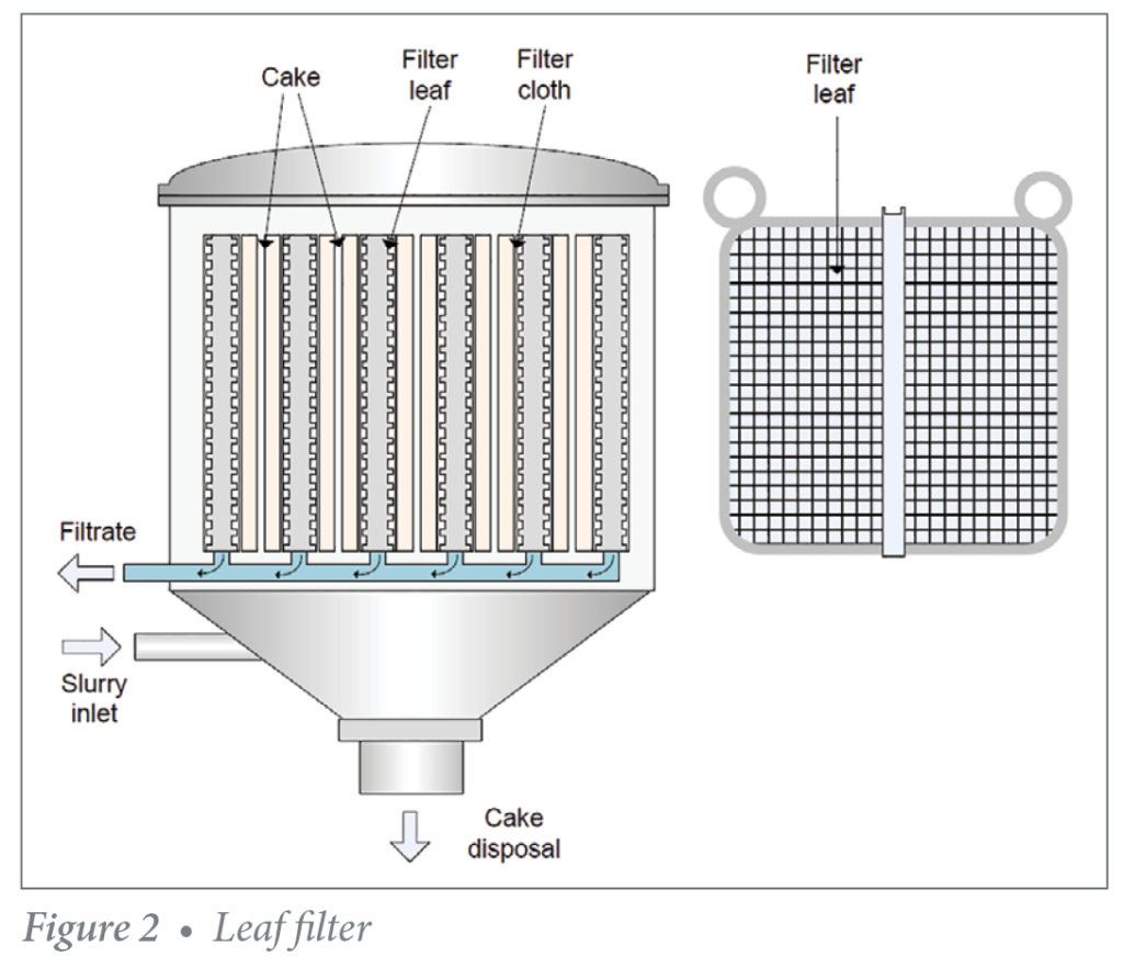
Leaf filters constitute a category of batch pressure filters that includes disc, candle and sheet filters.4 Leaf filters are similar to plate-and-flame filters in that a cake is deposited on each side of a leaf, and the filtrate flows to the outlet in the channels provided by a coarse drainage screen in the leaf between the cakes.
The leaves are immersed in the sludge when filtering, and in the wash liquid when washing. Therefore, the leaf assembly may be enclosed in a shell, as in pressure filtration, or simply immersed in sludge contained in an open tank, as in vacuum filtration.5 Filters are designed to take several leaves. For example, a 914 mm diameter filter can take between 6 and 13 filters while an 1828 mm diameter filter can take 20 leaves. Filtering areas of 100–300 m², operating at pressures of up to 600 kPa are common.6
In operating a pressure leaf filter, the sludge is fed under pressure from the bottom and equally distributed. The clear filtrate from each leaf is collected in a common manifold and carried away. In filters with an external filtrate manifold, the filtrate from each leaf is visible through a respective sightglass. This is not possible when the leaves are mounted on a hollow shaft that serves as an internal filtrate collecting manifold. The filter cakes are built on each side of the leaves and filtration is continued until the required cake thickness is achieved.
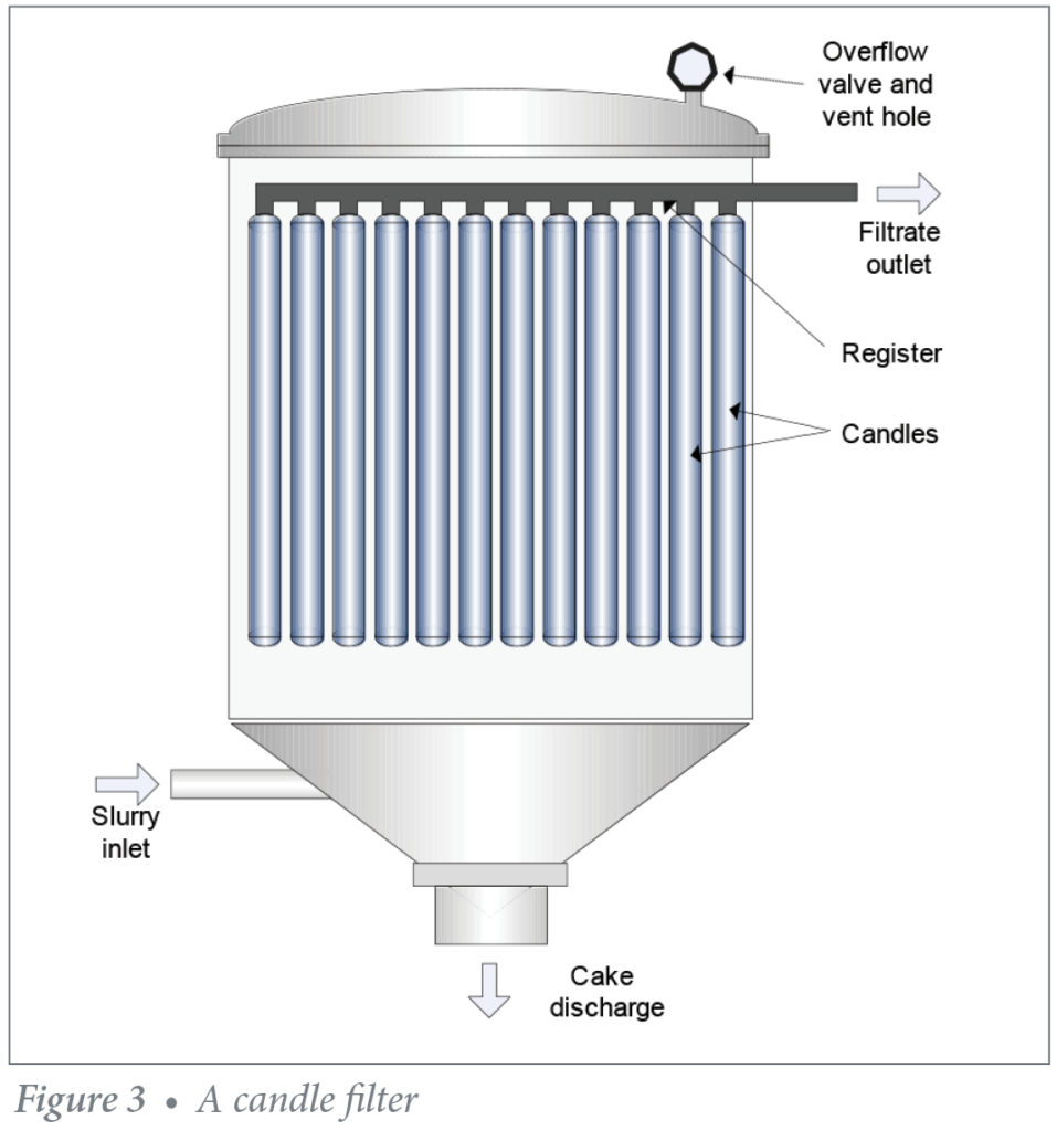
Candle Filters
Candle filters are leaf filters and are used for pressure filtration under discontinuous conditions. A candle filter comprises a number of filter elements, or ‘candles’, housed in a pressure vessel. Filtration is out-to-in, with the elements themselves formed from a support covered with a tubular filter cloth.4 Filtrate usually flows through the top of each element into a central manifold. The elements are suspended vertically in a pressure vessel, with a valve system in the base of the unit to allow for cake discharge.
The candle filter is a highly versatile process filter, mainly used for the recovery of process residues from liquid streams, typically with middle solid concentrations. Candle filters can be used for all manner of operations including filtration, cake washing (e.g. by flooding the vessel with wash water or spraying a fine mist of wash liquid as air or nitrogen is blown through the filter) and cake drying with hot gas. They offer excellent cleanability, using steam or Clean-In-Place liquids (CIP) and can deal with variable process conditions, e.g. erratic solids concentration.
Candle filters are used for sophisticated processes and often incorporate sensors to measure liquid level or cake thickness. The pressure vessel may have a viewing porthole. The filtering element can be almost any kind of cylindrical structure, but is ideally a rigid, smooth-surfaced tube, or bundle of tubes made from porous metal or plastic.
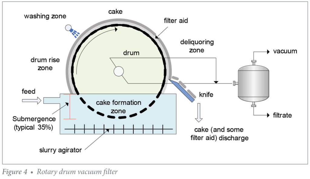
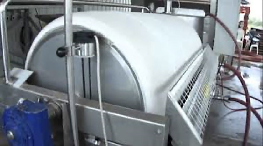
Rotary Drum Vacuum Filters
In simple words, rotary drum vacuum filtration consists of a drum rotating in a tub of liquid to be filtered. The drum is pre-coated with a filter aid, typically of diatomaceous earth (DE) or perlite. Rotary drum vacuum filters are widely used for recovery of solids from liquid suspensions. The technique is well suited to slurries, and liquids with a high solid content, which could clog other forms of filtration mechanisms. These types of filters support continuous filter cycles, thus are differentiated from the batch variants by the manner in which filter cake is continually formed, processed and subsequently discharged without interruption.7
The rotary drum vacuum filter offers:8
- Continuous Operation
- Application Versatility
- Wide Range of Sizes
- High cake-washing efficiency
- Low specific power requirements
A rotary drum vacuum filter consists of a drum rotating in a tub of liquid to be filtered. Prior to filtration of the feed, a suspension of precoat is filtered under vacuum onto the drum surface to a depth between 4 and 15 cm. The feed is then introduced and filtration proceeds to cause a thin, some-times gelatinous, cake to form on the surface of the precoat, penetrating the precoat to a depth of 0.5 mm or less. The final cake, along with some precoat, is removed using a knife or blade which progressively advances at rates as low as 5μm per drum revolution. In this way the filtering surface is continually renewed to maintain good permeability.
The process of the rotary drum vacuum filtration is continuous. Each revolution of the drum consists of cake formation, cake washing (optional), dewatering or drying, and cake discharge. As the drum rotates, it is partially submerged in the feed slurry. The vacuum draws liquid through the filter medium on the drum surface which retains the solids. Suction is applied using a liquid ring vacuum pump or other means. The vacuum pulls air (or gas) through the cake and continues to remove moisture as the drum rotates. Finally, the cake is discharged from the drum to a conveyor or chute to the next process step.
The filtrate and air pulled through the medium flow through internal filtrate pipes and pass though the rotary valve and into the filtrate receiver. The liquid stream is separated from the vapor stream in the receiver. Liquid filtrate is then pumped to the next step in the process. If required, the cake can be washed to remove impurities or to extract more product. Additional drying of the cake follows washing.
Precoating and Filtration Process
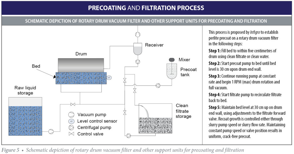
The process detailed in Figure 5 is proposed to establish perlite precoat on rotary drum vacuum filter, and consists of 5 steps:
Step 1: Fill bed to within five centimeters of drum using clean filtrate or clean water.
Step 2: Start precoat pump to bed until bed level is 30 cm upon drum end wall.
Step 3: Continue running pump at constant rate and begin 1 RPM (max) drum rotation and full vacuum.
Step 4: Start filtrate pump to recirculate filtrate back to bed.
Step 5: Maintain bed level at 30 cm up on drum end wall, using auto or manual operator adjustments to the filtrate forward valve. Recoat growth is controlled either through slurry pump speed or slurry flow rate. Maintaining constant pump speed or valve position results in uniform, crack-free precoat.
High concentrations of filter aid may be used in the precoat tank (10-15% or more by weight of slurry). The slurry pump speed should not exceed a rate which produces more than 2.5 cm of cake growth in ten minutes, since in rapid formation cake becomes excessively permeable. With precoating completed, the raw liquor pump may be started, the bed level raised, drum speed slowed, and filtrate put forward. The precoat should be allowed to seal over with liquor solids before the knife is advanced.
Variations in thickness and firmness between adjacent layers of the precoat cause variations in resistance to vacuum force, variable permeabilities to liquid flow, and unequal resistances to precoat cake compression forces. This unequal resistance effect can be characterized as layering, or soft-hard variations by strata. When excessive, it can cause cracking in any precoat.
When desired precoat thickness has been achieved, maximum precoat firmness is assured by allowing filtered liquor solids to deposit on the precoat surface, compressing the precoat fully before advancing the knife to begin cutting.
With the filter on-stream, filter throughput may usually be increased by increasing drum rotation rate, increasing drum submergence level, or increasing cutting rate. Conversely, precoat life and filter cycle length are usually prolonged by decreasing drum rotation rate, using drum submergence, and decreasing cutting rate as much as possible. As in precoating, on-stream filter operations are enhanced by consistency in drum speed, drum submergence, and knife rate.
With all filter aids, the watchword for optimum rotary vacuum precoat filter performance is uniformity in precoating.
Optimum Conditions for Best Performance Filtration
Best results in applying perlite filter aid to a rotary vacuum precoat filter are achieved when using 2-4% filter aid solids concentration by weight of slurry, well-agitated precoat slurry tank, constant precoat slurry liquid level in filterbed (preferably submerging drum to approximately 10% of drum diameter), drum rotation speed at approximately 1 RPM and constant vacuum airflow volume at 20 m3/hour per m² of filter drum surface. Every effort should be made to ensure that the value of each of the above parameters is held constant. Varying any factor will change the deposition rate of the surface layers of the precoat. Dissimilarity in deposition rate causes dissimilarity in the thickness and hence the firmness of adjacent layers within the precoat.
Troubleshooting
Like any other filter aid material, certain trouble-shooting issues may arise in the process of filtration. The main sources of failure relate to the filtration procedure itself, or the choice of filter aid grade. The good news is that solutions are simple and can be applied by the trainer operator to ensure smooth filtration.
LOW FLOWRATE
In case of low flowrate it is suggested the use of coarser grade of filter aid that will increase the paste porosity thus allowing more space for the liquid to pass.
TURBIDITY ISSUES
The inability of the process to remove ultrafine particles may lead to unsatisfying clarity to the final product. The addition of one part fine perlite filter aid as bodyfeed will address that issue by retaining the undesirable fine particles.
BLEED THROUGH
The collapse of the filter aid layer can be overcome by the addition of one part coarser filter aid grade while at the same time reducing the layer thickness.
Benefits of Perlite Over Diatomaceous Earths
Diatomaceous earth (DE), or simply diatomite, is made from the fossilized remains of tiny, aquatic organisms called diatoms. Their skeletons are made up of a natural substance called silica. Over a long period of time, diatoms accumulate in the sediment of rivers, streams, lakes, and oceans. This material is mined and calcined (heated at high temperature) to destroy any organic matter and agglomerate the diatoms together to achieve different rates of flow. The diatomaceous earth is then milled and separated into various filter aid grades through the use of air flotation.
Perlite filter aids are functionally like DE filter aids, and in fact, are used interchangeably in many situations where the collected solids are not wanted for subsequent treatment. However, the different origin and physicochemical properties render perlite advantageous in the following ways:
- A wide network of perlite suppliers is established assuring quick and uninterrupted local supply. This is not always the case for DE, which has long lead times and requires significant inventories to account for variations in demand.
- Perlite has 30-50% less bulk density thus comparable filter applications typically require 30%-50% less additive (by weight).9
- Perlite filter aids form lower density cakes than diatomite filter aids of comparable or better permeability and filtration fluxes, thus reducing the cost of disposal per ton of spent filter-cake generated.8
- Perlite filter aids generally contain no, or very little crystalline silica, thus do not pose a health hazard.
- As a consequence of its inert nature, perlite filter cake is not subject to strict regulations governing its disposal.
- DE possesses higher soluble iron that may affect the quality of edible and drinkable products.10
Replacement of Diatomite with Perlite Filter Aid
If a diatomite filter aid has previously been in use, determine the proper perlite filter aid precoat batch weight by multiplying the known precoat batch weight of the competitive diatomite material by the weight usage factor based on the density characteristics of perlite. This calculation will determine the weight of perlite filter aid which will provide an equal volume of disposable filter medium to replace the competitive diatomite. Alternatively, the amount of precoat required can be determined as follows once a few variables can be confirmed:
- Surface area to be precoated (m2)
- Desired thickness of the precoat (m)
- Wet density of the ÿlter aid to be used (kg/m3)
The calculation is simple: Mass of filter aid required (kg) = Surface area (m2) x Desired Thickness (m) x Wet Density (kg/m3)
Consistency in the rate of precoat application is of paramount importance in rotary vacuum filter precoating since it maximizes precoat uniformity. When the following conditions are allowed to vary the precoat application rate will vary:
- Concentration of filter aid solids in the filterbed slurry
- Submergence level of drum in filterbed slurry
- Speed of drum rotation in filterbed slurry
- Vacuum airflow volume in use
- Application Versatility
BIBLIOGRAPHY
[1] Gupta A, Yan D, eds. Solid Liquid Separation-Filtration. In: Mineral Processing Design and Operations. An Introduction. Elsevier; 2016:507-561.doi:10.1016/b978-0-444-63589-1.00015-0
[2] Perlmutter BA. Types of Filtration Systems. Solid-Liquid Filtr. 2015:35-45. doi:10.1016/b978-0-12-803053-0.00003-1
[3] Dicalite. A World of Filtration Experience.
[4] Sparks T, Chase G. Solid–Liquid Filtration. Filters Filtr Handb. 2016:199-295. doi:10.1016/b978-0-08-099396-6.00004-6.
[5] Cheremisinoff NP. Industrial Filtration Equipment; 1998. doi:10.1016/b978-075067047-0/50005-2
[6] Halberthal J. The vertical pressure leaf filters. www.solidliquid-separation.com/pressurefilters/verticalleaf/verticalleaf.htm. Accessed May 25, 2020.
[7] Tarleton ES, Wakeman RJ. Process design for continuous separations. Solid/Liquid Sep. 2007:329-382. doi:10.1016/b978-185617421-3/50007-9
[8] Sutherland K. Filters and Filtration Handbook. 5th ed. Butterworth-Heinemann; 2008.
[9] Cheremisinoff NP. Filter Media and Use of Filter Aids. Liq Filtr. 1998:19-58. doi:10.1016/b978-075067047-0/50003-9
[10] Jackson RS. Post-Fermentation Treatments and Related Topics.; 2014. doi:10.1016/b978-0-12-381468-5.00008-7
To download a .pdf of the Perlite Filter Aid (PFA) for Vacuum & Pressure Filtration brochure, click here.
If you have technical questions on this topic, please email the technical contacts listed on our contact page.
Copyright© 2021 Perlite Institute All Rights Reserved